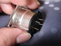
Unfortunately since I failed on two counts with my order, I seem rather inept at ordering what I want! Firstly I got three 3-pin connector's, 2 female, one male. And secondly all of the connectors I got were vertical mounting, not horizontal which is what I was expecting! Of course if I'd have been thinking enough I'd have realised this before! So lets look at the part number used, "NC5FDM3H"...
First it looks like the "NC5" is the important bit for a 5-pin connector, (not the M3 on the letters near the end of the reference, as I thought since the image of the M3-H on the website had 5 pins). Secondly, despite the website saying Horizontally mounted pins, I for some reason went and got vertically mounting ones!
While this doesn't matter in the grand scheme of things since I'll just solder some wires to the connectors, and the lights I plan on getting all require 3-pin connector's anyway, it is still a little annoying!
It turns out the M3 version of the connector has M3 threaded holes in the connecting plate so that it can be behind the plastic outside with a bolt through, while the other one has counter-sunk holes. Of these, I definitely prefer the M3 version because it means that only the socket and screws will be visible.
Anyway here's the picture of the bits I got:
I had anopther N00B moment while looking at the individual connector's trying to figure out how they can be 'locked' into place. Eventually I realised that the entrance to the hole you can use a tiny screwdriver to turn the locking mechanism is actually at the front of the socket, not the back! Also it appears as though there is a fourth pin which is there purely so the locking mechanism doesn't get lost when unlocked, the pin appears removable once the component is all installed and locked properly.
Top Left: Female 3-Pin socket
Top Right: View of the pins for the socket
Bottom Left: You can just about see the screwdriver shaped slot in the 4th hole
Bottom Right: Opening the socket when unlocked


No comments:
Post a Comment