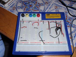
Lets start with the obvious item required... First I needed a breadboard to save lots of Solder:
The picture is one of the two breadboards I got. While I only needed the one, it is nice to be able to create two circuts. The wires on the picture come from some of my initial programming attempts to program the 16F chip I received from the Microchip samples.
Bread board is good because certain lines of holes are all connected to each other. You plug in the chip across one of the gaps, then use the holes next to the pins required, plugging in wires to those holes to make up the circuits required.
I already had a nice variable power supply, it can be set to output varying voltage levels through a number of connectors. While my programmer, (I'll describe that later), can be used to power the circuit board, it is always nice to have a transformer which can be used to run the board directly.
A nice little toolkit, including some nice little pliars, and varying screwdrivers. The Pliars are useful for holding annoyingly little cables, the screw drivers have been useful for changing variable resistors. Overall the most useful and most used item here are the wire clippers on the left.
The picture above shows a few electronics sets I bought... A box of various LED's, (mini lights which can be used to show the state of various output pins from Microchip pins). A pack of many resistors, hopefully all I will ever need, (and yes we will need quite a few!), and similarly a pack of many capacitors as well, (and once again we need some of them). The picture also shows a number of wires, (the solid core wires as they pin into the breadboard well, not the mult-core wires which are better to bend and move as they are more flexible). Finally there is also a wire stripper tool there which is great for stripping the edges off the various wires allowing them to be plugged into the breadboard ;-).
Other items got to help with the electronics includes a crystal, (to control the clock speed of the processor), A keypad (to test input via a keypad), a 16 character by 2 line LED display screen, various potential divider resistors and a slider potentiometer.
A voltage meter (above) was also bought to help see the various circuit variables. I went a bit further than just the cheapest voltmeter, getting one with various extra functions including resistance, current and frequency. Since the price wasn't massively more for the increased functionality, I think it was best to get the extra functions.
Finally I needed a PIC programmer. A device to used to copy the program code written on a PC, compiled into bytes which the microprocessor can then understand and run. I went for the PICkit 2 programmer, ordered from the Microchip site, it even came with a sample 44-pin test board containing various buttons, LED's and sample programs.
Overall the PICKit was probably one of my better buys. The conjunction of the programmer and test board really helped creating and testing some basic programs.
The wires coming out of the PICkit programmer were put together using some wires I saw containing pre-set pins on the ned of each wire. Since I plug them into and out from the breadboard quite a bit. The tape just holds the wires at the right distance apart. In reality I should find some pins I can plug into the breadboard just like the sample test board.


No comments:
Post a Comment