First of all I plugged in the Microchip across one of the gaps, (the breadboard links all the main section holes across horizontally between each gap). In order to do this I had to push the pins in a bit to make them 90 degree's from the chip, (by default they splay out a bit). Do this by placiong the pins against a flat edge (like on a table) and push them in together, don't do it by pushing each pin in individually as that will tend to result in pins not all being pushed in the same amount. Once they were flat I put the chip into the breadboard:
The next thing to do is to wire the chip up so that I can plug in the PICkit 2 device... While I could put wires from the PICkit device into any slot on the board, I like having them all next to each other so I can plug the device in easily.
The PICkit device has 6 connections, of which one is not used. The remaining five pins, and the corresponding pin numbers on the main microchip are as follows:
- Vpp/MCLR - Pin 1
- VDD Target - Pin 20
- VSS (Ground) - Pin's 8 & 19
- ICSPDAT/PGD - Pin 28
- ICSPCLK/PGC - Pin 27
The picture above shows how I placed the connections. The Vss and Vdd lines have been passed up to the top bar as well for any main Vsource/ground connections.
In order to have a method of telling if the miocroprocessor is powered, I then added a simple LED and resistor between the Vdd and Vss rails on the left hand side of the board. The resistor I used was a 1K resistor, (which oddly I seem to be running short on as they seem to be used a lot). This results in an LED lighting up when the circuit has power, (either through an external power source, or through power supplied by the PICkit USB interface.
The image above shows the LED being on with external power supplied to the base breadboard. Of course the microprocessor isn't doing anything here, although it is powered. In order to check that the connection to the PICkit works correctly we need to disconnect that external power and connect the PICkit device...
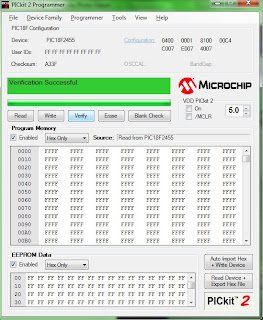
Then running the PICkit software, and clicking the Verify button checks the connection and passes back a little information about the processor and its current memory. Since the device is correctly identified and Verified, I think I can assume that the PICKit connection is working correctly:
The next thing would be to set up an Oscillator so that the chip has its own clock source. Eventually we should be using an external crystal which should help to provide the signal, however based on the Data Sheet, there should be an internal clock source, however using this will mean that USB won't work until we have an external source... But since that's a while away, I think we can forget about that for now. Provided of course I can get the internal oscillator to work...
However that is going to have to wait for later as I'm hungry now and want a break! So next up should be a simple application to flash an LED... Which means I guess we'll need another LED adding to that basic circuit...


No comments:
Post a Comment